UA-188078797-1

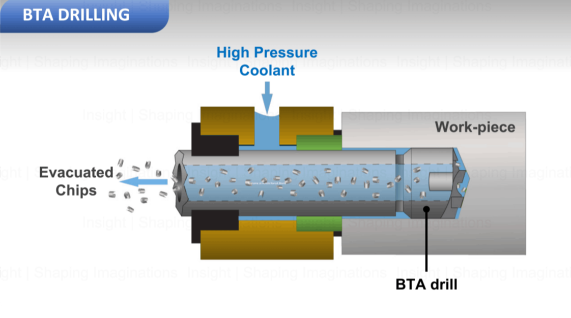
What is BTA Drilling?

BTA drilling process and it's key technical considerations

BTA drilling is a highly specialized drilling process that offers exceptional precision and efficiency for deep hole drilling applications. By understanding the recommended cutting parameters, tool geometry, coolant requirements, machine features, and mechanical aspects, manufacturers can optimize BTA drilling processes for various industries.
With its ability to achieve tight tolerances and excellent surface finish, BTA drilling plays a vital role across a wide array of industries that require deep hole drilling operations such as
▸ Oil and Gas
▸ Automotive
▸ Aerospace
▸ Energy
▸ Defence
▸ Heavy Machinery
▸ Medical Device Manufacturing
▸ Construction Equipment

A few application examples:
▸ Oil and Gas Industry: BTA drilling is extensively used in the oil and gas sector for drilling long, straight, and accurate holes in components such as drill collars, production tubing, risers etc.
▸ Automotive Industry: In the automotive sector, BTA drilling finds applications in manufacturing components like engine blocks, transmission shafts, suspension tubes, drive axles, etc., where deep holes with high precision are crucial.
▸ Aerospace Industry: BTA drilling is employed in the aerospace sector for drilling holes in turbine components, landing gear, airframe structures, to name a few - ensuring high-quality and reliable performance.

Comparison to Gun Drilling:
Gun drilling is a conventional deep hole drilling process that is often compared to BTA drilling. While both processes are suitable for deep hole drilling, they have distinct characteristics. Gun drilling typically achieves higher aspect ratios (L/D ratios) and is well-suited for smaller diameter holes. BTA drilling, on the other hand, is more suitable for larger diameter holes and offers better chip evacuation and surface finish control.

Gun Drilling, BTA Drilling, Deep Hole Drilling

Cutting Parameters for BTA Drilling

Feed Rate:
Feed rate in BTA drilling refers to the rate at which the cutting tool advances into the work-piece during the drilling process. It is an important parameter that directly affects the drilling efficiency and quality. The feed rate should be carefully selected based on factors such as work-piece material, diameter, and length, as well as the desired cutting speed and chip evacuation. A proper feed rate ensures optimal chip formation, efficient chip evacuation, and helps maintain tool life and dimensional accuracy. It is typically measured in millimeters per revolution (mm/rev) and should be adjusted accordingly to achieve the desired drilling results in BTA drilling operations.
The recommended feed rate in BTA drilling typically ranges from 0.05 mm/rev to 0.5 mm/rev, depending on the work-piece material, diameter, and length.

Cutting Speed:
Cutting speed in BTA drilling refers to the peripheral speed at which the cutting tool rotates during the drilling process. It is a crucial parameter that directly impacts the cutting efficiency, tool life, and surface finish. The cutting speed is determined by the work-piece material and should be carefully selected to optimize the balance between material removal rate and tool wear. A higher cutting speed increases the heat generation and forces on the cutting tool, necessitating the use of appropriate cutting fluids for cooling and lubrication. Conversely, a lower cutting speed may result in prolonged machining times. By choosing the right cutting speed for BTA drilling, manufacturers can achieve efficient material removal while maintaining the desired surface finish and prolonging tool life. Cutting speed is typically measured in meters per minute (m/min) in BTA drilling operations.
The cutting speed in BTA drilling should be adjusted based on the work-piece material. Typical cutting speeds vary from 30 m/min to 150 m/min.

Cutting Fluids and Compositions

Cutting fluids play a critical role in BTA drilling by providing lubrication, cooling, and chip evacuation. They are essential for enhancing tool life, improving surface finish, and maintaining dimensional accuracy. In BTA drilling, water-soluble cutting fluids or emulsions are commonly used. These cutting fluids are typically composed of a mixture of water, base oil, and various additives. The composition of cutting fluids can vary depending on the specific application and work-piece material. Additives such as lubricity enhancers, corrosion inhibitors, and anti-foaming agents are often incorporated to improve the performance of the cutting fluid. The selection of cutting fluid composition should consider factors such as work-piece material compatibility, machining conditions, and environmental regulations. Proper application of cutting fluids in BTA drilling helps to reduce friction, dissipate heat, flush away chips, and prolong tool life, ultimately leading to efficient and high-quality drilling operations.

Coolant Pressure and Coolant Flow Rate:
Recommended coolant pressure and coolant flow rate are crucial factors in BTA drilling to ensure effective chip evacuation, cooling, and lubrication. The coolant pressure should be set within the range of 20 bar to 50 bar (290 psi to 725 psi) to provide sufficient force for chip removal and prevent chip clogging. A higher coolant pressure helps in flushing away chips and maintaining a clean cutting zone. However, it is important to balance the coolant pressure to avoid excessive fluid usage and potential tool wear. In terms of coolant flow rate, it should be adjusted to ensure adequate cooling and lubrication of the cutting tool and work-piece. The recommended coolant flow rate in BTA drilling depends on the specific drilling parameters, such as tool diameter, cutting speed, and work-piece material. A proper coolant flow rate helps in dissipating heat, reducing friction, and prolonging tool life. By optimizing coolant pressure and flow rate, manufacturers can achieve efficient chip evacuation, maintain appropriate tool temperature, and improve overall drilling performance in BTA operations.

BTA drilling Tool & basic geometry

The tool geometry in BTA drilling is carefully designed to meet the specific requirements of deep hole drilling operations. The BTA tool typically consists of multiple components, including the drill body, inserts, guide pads, and a backstop. The drill body is designed to provide stability and support to the cutting inserts. The inserts feature a special geometry with cutting edges optimized for chip formation and evacuation. They are usually made from carbide or high-speed steel, chosen based on the work-piece material and drilling conditions. The cutting inserts come in various geometries (round, square, triangular) based on application requirements.
The guide pads help maintain the alignment and stability of the drill during the drilling process. The backstop, positioned behind the inserts, prevents excessive tool deflection and assists in accurate hole positioning. The overall tool geometry is carefully engineered to achieve efficient chip evacuation, minimize cutting forces, and ensure dimensional accuracy and surface finish. The selection of appropriate tool geometry is crucial for successful and productive BTA drilling operations.

Rake Angles and Clearance Angles:
The recommended rake angle for BTA drilling is typically around 6° to 10°. As for the clearance angle, a value between 6° and 10° is generally suitable. These angles help optimize chip formation and evacuation, reduce cutting forces, and improve tool life.

BTA Drilling Tool

Effect of kinematics on hole axis in Gundrilling

Tool Spindle & Feed Axis

Most BTA drilling machines employ tool spindles with angular contact ball bearings for precision and stability. Angular contact ball bearings offer high rigidity, load capacity, and accuracy, ensuring smooth operation during drilling.

Tool spindle drives in BTA drilling machines may vary depending on the specific machine design. Some common types include direct drive, belt drive, and gear drive. The choice depends on factors such as torque requirements, speed control, and machine architecture.

Feed Axial drives in BTA drilling machines are responsible for managing axial forces and ensuring stability during drilling. One common type of axial drive is the ball-screw drive with a servomotor. The servomotor provides precise control over the axial feed, allowing for accurate drilling depths and chip evacuation.

Applications insights on BTA drilling

Materials:
BTA drilling is applicable to a wide range of work-piece materials, including steels, stainless steels, superalloys, non-ferrous metals, and composites. The diameter range typically starts from 20mm and can extend up to 1000mm, while the maximum achievable length may reach up to a staggering 20 meters.

Dimensional and Geometric Tolerances:
BTA drilling is renowned for its ability to achieve high dimensional and geometric tolerances. Achievable dimensional tolerances can be as tight as ±0.02 mm per diameter. Geometric tolerances, such as straightness, concentricity, and cylindricity, can be held within microns.

Surface Roughness:
With appropriate cutting parameters and tool geometry, BTA drilling can achieve surface roughness values (Ra) ranging from 1 to 6 micrometers. Additional post-processing techniques, such as honing or burnishing, can be employed to further improve the surface finish if required.

BTA drilling Process Ranges

BTA drilling is the ideal process for a wide range of deep hole diameters & hole depths. BTA drilling is capable of drilling quite extreme L/D ratios with quite tight tolerances.

Diameter Range (in mm):
⌀8 to ⌀65. : Brazed type perishable tool
⌀10 to ⌀114 : Spade drill type
⌀16 to ⌀28. : Indexable type single Insert
⌀ 25 mm + : Indexable type with multiple Inserts

BTA tool heads come in various configurations such as brazed tip consumable type - for low production volumes, indexable insert type for high production volumes, and so forth, each one serving a purpose of its own.

BTA Drill Heads

General types of BTA Tool Heads

Architecture of BTA drilling machines

Configurations:
1) Vertical BTA Machines: Vertical BTA machines are designed for drilling operations where the work-piece is held vertically. They are suitable for various applications, including automotive, aerospace, and oil and gas industries.
2) Horizontal BTA Machines: Horizontal BTA machines are used when the work-piece is held horizontally, and drilling is performed along the horizontal axis. These machines are commonly used in industries such as energy, heavy machinery, and defense.

Spindle matrices:
1) Single-Spindle BTA Machines: These machines feature a single spindle and are suitable for drilling applications with lower production volumes or smaller work-pieces.
2) Multi-Spindle BTA Machines: Multi-spindle BTA machines have multiple spindles, allowing simultaneous drilling of multiple holes. These machines are ideal for high-volume production and larger work-pieces.

Key Features of BTA Drilling Machines

▸ Rigid Machine Structure: BTA machines are designed with a robust and rigid structure to minimize vibrations and ensure accurate drilling.
▸ Programmable Spindle Speed and Feed Rate: BTA machines offer the flexibility to adjust spindle speed and feed rate according to work-piece material and drilling requirements.
▸ Chip Evacuation System: Effective chip evacuation is critical in BTA drilling. BTA machines are equipped with efficient chip evacuation systems to remove chips from the drilling zone, preventing chip clogging and ensuring uninterrupted drilling.
▸ Coolant System: BTA machines feature high-pressure coolant systems that deliver cutting fluid to the cutting zone, providing efficient cooling, lubrication, and chip evacuation.

Mechanical Aspects of BTA Machines:
▸ Spindle Power and Torque: BTA machines employ powerful spindles capable of providing high torque to handle the demanding drilling requirements of deep hole applications.
▸ Axial Thrust Control: BTA machines incorporate axial thrust control mechanisms to manage and minimize the axial forces generated during drilling. This ensures stability, accuracy, and reduced tool wear.
▸ Precision Guideways: BTA machines utilize precision guideways to maintain accurate alignment and enable smooth movement during the drilling process, enhancing overall drilling performance.

Key Components of BTA Drilling Machines

Typical BTA drilling machines consist of several key components that contribute to the accuracy, efficiency, and reliability of the drilling process.

Drill Guide Bushing:
The precision drill guide bushing is an essential component in BTA drilling. It serves to guide the BTA tool during the initial drilling phase, ensuring accurate hole positioning and diameter. The drill guide bushing also acts as a seal against the workpiece, effectively containing the coolant during the drilling process.

Pressure Head:
The pressure head surrounds the BTA tool and drill guide bushing, playing a vital role in coolant delivery and chip evacuation. It introduces coolant around the outside of the tool to provide effective cooling and lubrication during drilling. Additionally, it aids in the efficient removal of chips throughout the drilling operation.

Vibration Dampeners:
Vibration dampeners are employed to stabilize long drills and mitigate vibrations caused by high rotational speeds. Equipped with rotating bearings and inserts, these devices come into contact with the tool, providing damping effects. Longer BTA machines may feature multiple traveling vibration dampeners to ensure optimal stability, while shorter machines may not require any.

Drilling Spindle:
The drilling spindle is responsible for transmitting power, torque, and rotation from the motor to the BTA tool. It is designed to deliver high power and torque precision while minimizing vibrations. Additionally, the spindle incorporates a central hole through which chips and coolant are evacuated during drilling operations.

Coolant System:
The coolant system is a critical aspect of BTA deep hole drilling, significantly impacting its reliability and performance. It typically consists of a carefully designed reservoir that holds coolant, and a high-volume pump responsible for delivering the cutting fluid to the BTA tool. As the coolant progresses through the metal cutting operation, it enters a filtration system designed to remove chips and small particles. The incorporation of low-micron coolant filtration and filter condition feedback helps prevent chip accumulation, resulting in reduced downtime, extended tool life, and improved surface finish.

Coolant Temperature Control:
Controlling coolant temperature is crucial in BTA drilling machines as the drilling headstock and coolant pumping system generate heat during operation. Elevated temperatures can negatively affect tool life, accuracy, and the overall machine environment. To manage heat, BTA machines employ either a heat exchanger or a chiller. These devices are responsible for maintaining the cutting fluid at an optimal temperature, ensuring efficient drilling performance and minimizing thermal effects on the drilling process.

These components work together to ensure precise drilling, efficient chip evacuation, and effective cooling and lubrication, contributing to the success of BTA drilling operations.

BTA Drilling Machine Key Components

General arrangement of BTA Drilling Head

Insight's iDrill DH-B Series | BTA Drilling Machines

Nomenclature
DH: Deep Hole | B: BTA drilling

BTA drilling machines were developed and engineered by Insight's domain experts over 2 decades back - ground up!

Over the years, engineering of Insight's machines has evolved comprehensively - culminating into machine building finesse. Let's discuss, evaluate and solve the challenges you may be facing in your deep hole drilling applications.

Click to explore iHone VR-S Series - Single Pass Honing Machines.

Click to explore iGrind LG Series - Dual Face Fine Grinding Machines